In the drawings of high-frequency transformers, when it comes to wiring methods, one often sees terms such as “Uniform winding“, “Close winding“, “Sparse winding“, and “Loose winding“. In this article, we will discuss the impact of wiring methods on the performance of high-frequency transformers.
“Uniform winding”, as the name suggests, refers to uniform winding, with uniform spacing between enameled wires. It can be divided into “uniform dense winding” and “uniform sparse winding”.
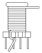
“Close winding” refers to the fact that enameled wires are closely arranged with no gaps between turns, achieving the highest winding density. Close-winding includes full-layer close-winding, mid-layer close-winding, and edge-side close-winding, etc. The specific arrangement should be determined based on the winding space and design.
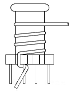
“Sparse winding” refers to the process where enameled wires are arranged sparsely and wound at certain intervals. Uniform sparse winding refers to the situation where the inter-turn spacing is the same, usually when the entire layer is not fully arranged, thus requiring uniform sparse winding more often.
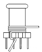
“Loose winding” lies between close winding and sparse winding. The enameled wires are arranged at larger intervals and the wiring is not uniform.
It is worth noting that many materials, for the sake of convenience, often do not provide very accurate annotations. This should be noted when browsing relevant drawings and winding products.
For instance, if some drawings uniformly state “tight winding”, it may involve various situations of tight winding. If it can just be wound around one or several layers, it represents “winding the entire layer closely”. If it is impossible to complete a full layer, it is called “closely winding in the middle”. If there are two windings on the same layer, there will be situations such as close winding by PIN or close winding by top, which are called “close winding by edge”.
Considering the conventional wiring methods of high-frequency transformers, this article mainly discusses the influence of three wiring methods – dense winding, sparse winding, and loose winding – on the performance of high-frequency transformers.
The closely wound enameled wire is compactly arranged, with a large number of turns per unit volume and a very high utilization rate of the magnetic core window. Its magnetic field is concentrated, the coupling efficiency is high, and the leakage inductance is relatively small. However, for close winding, it is necessary to strictly control the damage to the wire during the winding process and ensure that the inter-turn insulation meets the basic requirements; otherwise, the wire will be burned out due to short circuits between the wires.
In addition, close winding will cause uneven current density distribution in adjacent conductors when the transformer operates at high frequencies, thereby increasing the AC resistance and losses. Tight winding can also lead to blocked air circulation, low heat dissipation efficiency and possible higher temperature rise. Secondly, close winding will also increase the distributed capacitance of the winding, which is prone to cause resonance at high frequencies.
Loose winding is the opposite of close winding. Its wire spacing is large, the number of turns per unit volume is small, and the window utilization rate is low. Its magnetic field distribution is scattered, the coupling efficiency is low, and the leakage inductance is relatively high. It has good heat dissipation effect, weak proximity effect and small distributed capacitance.
The performance of the sparse winding lies between that of the dense winding and the loose winding. Its overall performance is excellent, balancing the requirements of window utilization, leakage inductance, distributed capacitance and heat dissipation.
In high-frequency transformers, it is often a combination of one or more winding methods. Considering the volume of the transformer, close winding is often adopted, which is conducive to the automated production of transformers. However, if it is impossible to fill one layer, then sparse winding will be considered, especially uniform sparse winding.
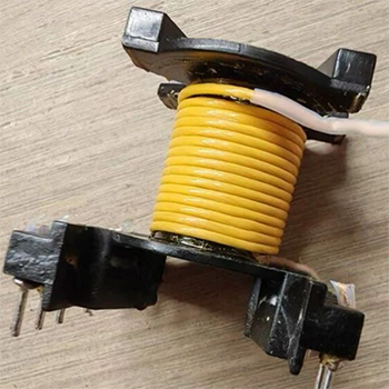
Loose winding is generally not adopted, but most transformers are manually wound. When the uniform loose winding is not in place, it will be closer to loose winding. In actual cases, this wiring method can be used for analysis.
Post time: Oct-30-2025